Description of Function
Overcurrent monitoring (OVER, OVER+LATCH):
When the monitored current exceeds the value adjusted at the MAX-dial, the
tripping delay (DELAY) begins (red LED MAX flashes). After the tripping delay
(DELAY) has expired (red LED MAX illuminated), the output relays switch into off position (yellow LED RELAY not illuminated). The output relays again switch into
on-position (yellow LED illuminated), when the monitored current falls below the
value adjusted at the MIN-dial (red LED MAX not illuminated).
If the fault latch is activated (OVER+LATCH) and the monitored current remains
above the MAX-value longer than the tripping delay, the output relays remain in the
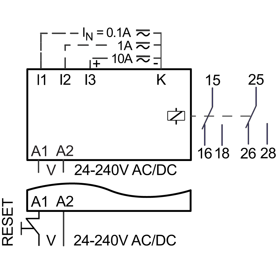
off-position even if the monitored current falls below the value adjusted at the MIN dial. After resetting the latch (interrupting and re-applying the control voltage), the
output relays switch into on-position and a new monitoring cycle begins with the
delay start-up suppression (START).
Undercurrent monitoring (UNDER, UNDER+LATCH):
When the monitored current falls below the value adjusted at the MIN-dial, the
tripping delay (DELAY) begins (red LED MIN flashes). After the tripping delay
(DELAY) has expired (red LED MIN illuminated), the output relays switch into
off-position (yellow LED not illuminated). The output relays again switch into on position (yellow LED illuminated), when the monitored current exceeds the value
adjusted at the MAX-dial.
If the fault latch is activated (UNDER+LATCH) and the monitored current remains
below the MIN-value longer than the tripping delay, the output relays remain in the
off-position even if the monitored current exceeds the value adjusted at the MAX dial. After resetting the latch (interrupting and re-applying the control voltage), the
output relays switch into on-position and a new monitoring cycle begins with the
delay start-up suppression (START).
Band (Window) Function (BAND, BAND+LATCH):
The output relays switch into on-position (yellow LED RELAY illuminated) when
the monitored current exceeds the value adjusted at the MIN-dial. When the
monitored current exceeds the value adjusted at the MAX-dial, the tripping delay
(DELAY) begins (red LED MAX flashes). After the interval has expired (red LED
MAX illuminated), the output relays switch into off-position (yellow LED RELAY not
illuminated). The output relays again switch into on-position (yellow LED RELAY
illuminated) when the monitored current falls below the value adjusted at the MAX dial (red LED MAX not illuminated). When the monitored current falls below the
value adjusted at the MIN-dial, the tripping delay (DELAY) begins again (red LED
MIN flashes). After the delay has expired (red LED MIN illuminated), the output
relays switch into off-position (yellow LED not illuminated).
If the fault latch is activated (WIN+LATCH) and the monitored current remains
below the MIN-value longer than the set interval of the tripping delay, the output
relays remain in the off-position even if the monitored current exceeds the value
adjusted at the MIN-dial. If the monitored current remains above the MAX-value
longer than the set interval of the tripping delay, the output relays remain in the off position even if the monitored current falls below the value adjusted at the
MAX-dial. After resetting the latch (interrupting and re-applying the control
voltage), the output relays switch into on-position and a new monitoring cycle
begins with the delay of the start-up suppression (START)
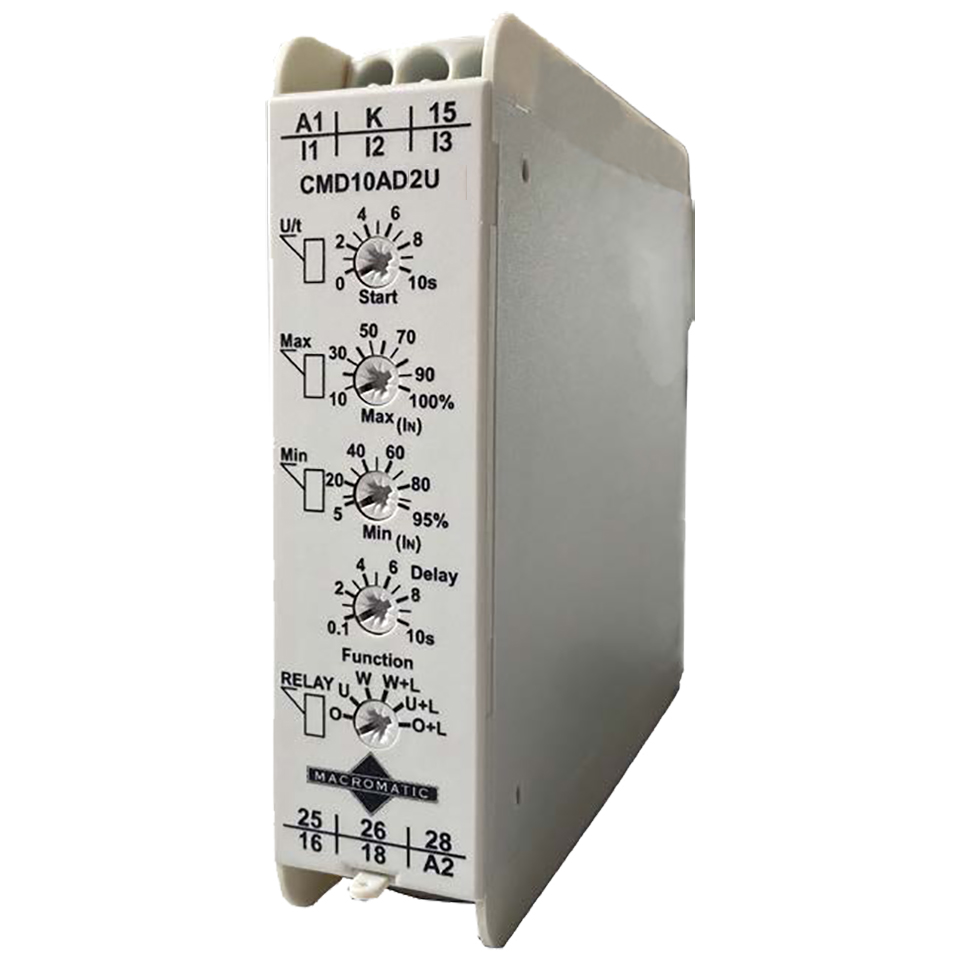


 CMD10AD2U