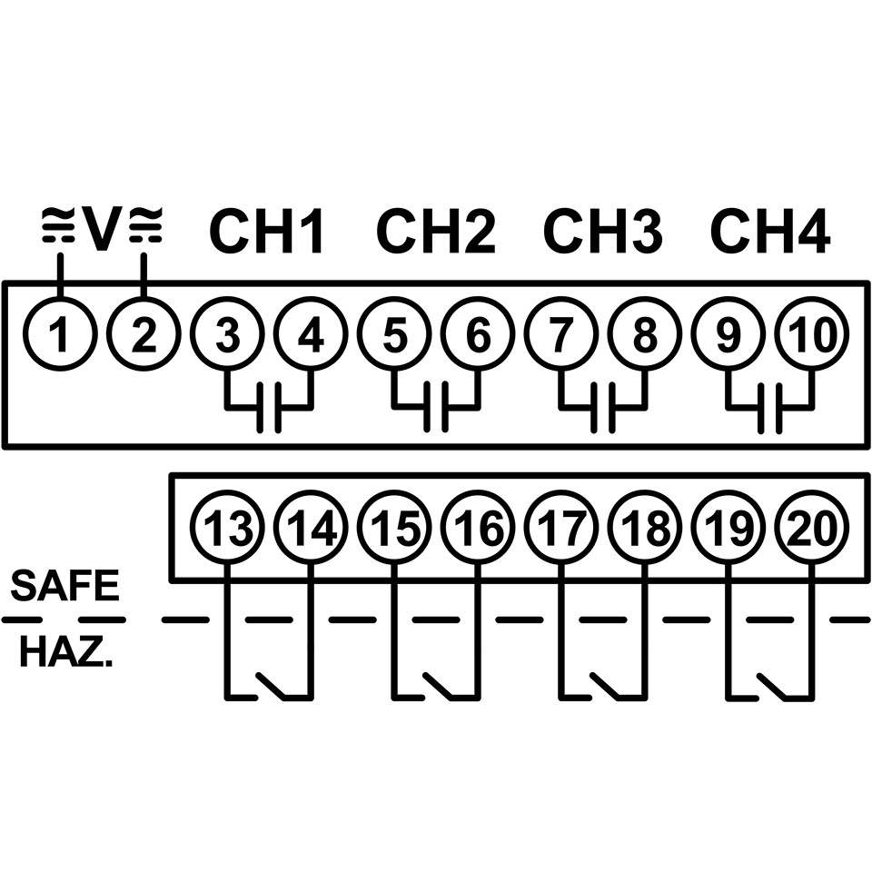
ISD Series
Description of Function
Each ISD Series product consists of 4 intrinsically safe inputs and 4 corresponding electromechanical relay outputs. With input voltage applied, the V LED will be ON (GREEN) to indicate power is applied. When the input device is closed, the input LED is ON (GREEN). When the output relay is energized, the output LED is ON (ORANGE).
These products offer four operating configurations which are user selectable and easily accessible.
ISDUM4 has an eight-position DIP-switch with configurations applied independently to each channel.
Configurations applied:
Standard Logic (DIP Switch set to “STD”):
When the input device in the hazardous area is closed, the corresponding output relay is energized. When the input device opens, the corresponding output relay will de-energize.
Inverse Logic (DIP Switch set to “INV”):
When the input device in the hazardous area is open, the corresponding output relay is energized. When the input device closes, the corresponding output relay will de-energize.
No Time Delay (DIP Switch set to “0 S”):
The output relay will have an immediate change in status in response to the input device closing or opening.
Fixed 2 Second Delay (DIP Switch set to “2 S”):
The output relay will delay 2 seconds before a change of status in response to the input device closing or opening.
Product Overview
Features:
Approved for use in these hazardous environments:
Class I, Div 1 (Zones 0 and 1 Canada), Groups A,B,C,D
Class II, Div 1 (Zones 20 and 21 Canada), Groups E,F,G
Class III, Div 1
4-Channel
Isolated input terminals
Isolated 5A relay outputs
Pluggable terminals offer easy installation & replacement
Universal input voltage of 102-132V AC & 10-125V DC
Standard & inverse logic
Instantaneous & delayed response times
LED status indicator
UL913 8th Edition
Enclosure Style:
DIN-rail
Configuration / Contact Rating:
SPST-NO (Form A) 3A Resistive @ 125V AC @ 60oC & 30V DC Resistive, Pilot Duty Rating D300 5A Resistive @ 125V AC @ 40oC & 30V DC Resistive, Pilot Duty Rating D300
Application Information:
Input Voltage: 102-132V AC (50/60Hz.) & 10-125V DC, Load (Burden): 5VA Maximum, Input Switch Open Circuit Voltage:10V DC, Output Contacts: SPST-O (Form A) 3A Resistive @ 125V AC @60°C & 30V DC Resistive, Pilot Duty Rating D300, SPST-NO (Form A) 5A Resistive @125V AC @40°C & 30V DC Resistive, Pilot Duty Rating D300, Life: Electrical: 50,000 Closures @ Full Load AC, Mechanical: 5 Million Closures @ No Load, Response Times: Standard (DIP Switch set to “0S”): < 50ms Delay (DIP Switch set to "2S"): Fixed 2 Seconds, Temperature: Operating: -28° to 60° C (-18° F to +140° F) Storage: -55° to 85° C (-67° to 185° F), LED Indication: V: ON (Green); Inputs: ON (Green); Outputs: ON (Orange), Insulation Voltage: 1500 V AC between coil & contacts, 750 V AC between open contacts, 1500 V AC between contacts of different output channels, 1500 V AC between hazardous and safe circuits, Wire Sizes: One#14-24 AWG Conductor or Two #16 or 18 AWG Conductors, Mounting: Mounts on 35mm DIN-Rail or panel-mounted with two #8 screws when DIN-rail clips are fully extended from under the enclosure, Control Drawing: See Instruction Sheet 901-0000-328, which includes Control Drawing ISD1A04
Approvals:


Operations
Each ISD Series product consists of 4 intrinsically safe inputs and 4 corresponding electromechanical relay outputs. With input voltage applied, the V LED will be ON (GREEN) to indicate power is applied. When the input device is closed, the input LED is ON (GREEN). When the output relay is energized, the output LED is ON (ORANGE). These products offer four operating configurations which are user selectable and easily accessible. ISDUM4 has an eight-position DIP-switch with configurations applied independently to each channel. Configurations applied: Standard Logic (DIP Switch set to : When the input device in the hazardous area is closed, the corresponding output relay is energized. When the input device opens, the corresponding output relay will de-energize. Inverse Logic (DIP Switch set to: When the input device in the hazardous area is open, the corresponding output relay is energized. When the input device closes, the corresponding output relay will de-energize. No Time Delay (DIP Switch set to: The output relay will have an immediate change in status in response to the input device closing or opening. Fixed 2 Second Delay (DIP Switch set to: The output relay will delay 2 seconds before a change of status in response to the input device closing or opening
Product Reviews
Do you have experience with this product? Leave us a review!
Add a review

Rating*
0/5
* Rating is required
Your review
* Review is required
Name
* Name is required
Email
* Email is required
0.0
Based on 0 reviews
5 star | 0% | |
4 star | 0% | |
3 star | 0% | |
2 star | 0% | |
1 star | 0% |
0 of 0 reviews
Sorry, no reviews match your current selections