• Voltage Tolerance:
AC Operation +10/-15% of nominal at 50/60 Hz
DC Operation -10/15% of nominal
• Load (Burden): Maximum of 4 VA
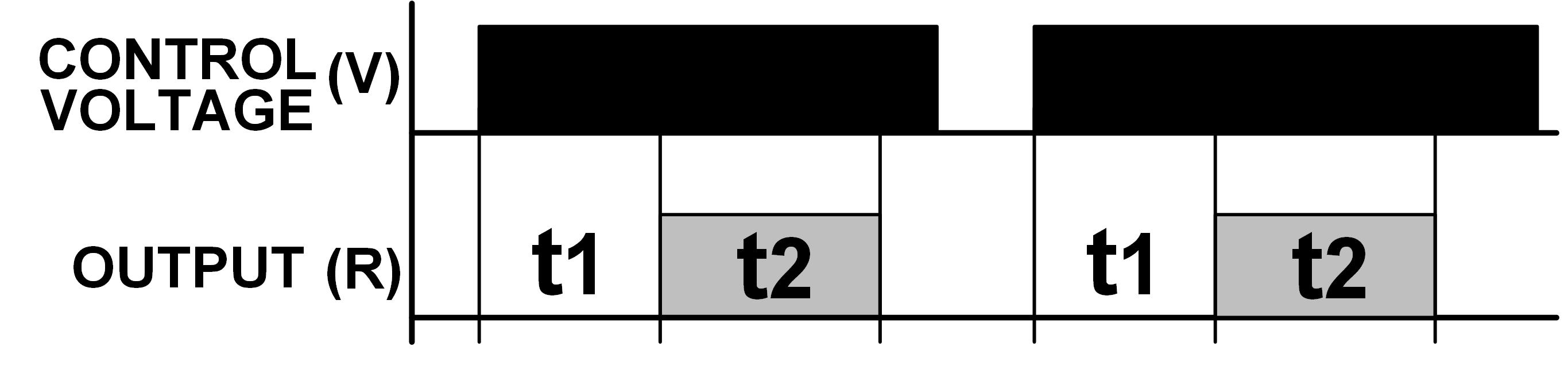
• Setting Accuracy:
Maximum Setting (adjustable): +5%, -0%
Minimum Setting (adjustable): +0%, -50%
Fixed Time Delay: ±2% or 50ms, whichever is greater
• Repeat Accuracy:
Constant Voltage & Temperature: ±0.1% or ±0.05 Seconds, whichever is greater
Variable Voltage & Temperature: ±5% or ±0.1 Seconds, whichever is greater
• Reset Time: 0.1 Seconds
• Start-up time: 0.05 seconds
• Maintain Function Time: 0.01 seconds
• Minimum Required Trigger Switch Closure: 0.05 seconds
• Temperature:
Operating: -28° to 65°C (-18° to 149° F)
Storage: -40° to 85° C (-49° to 185° F)
• Life:
Mechanical: 10,000,000 perations
Full load: 100,000 operations
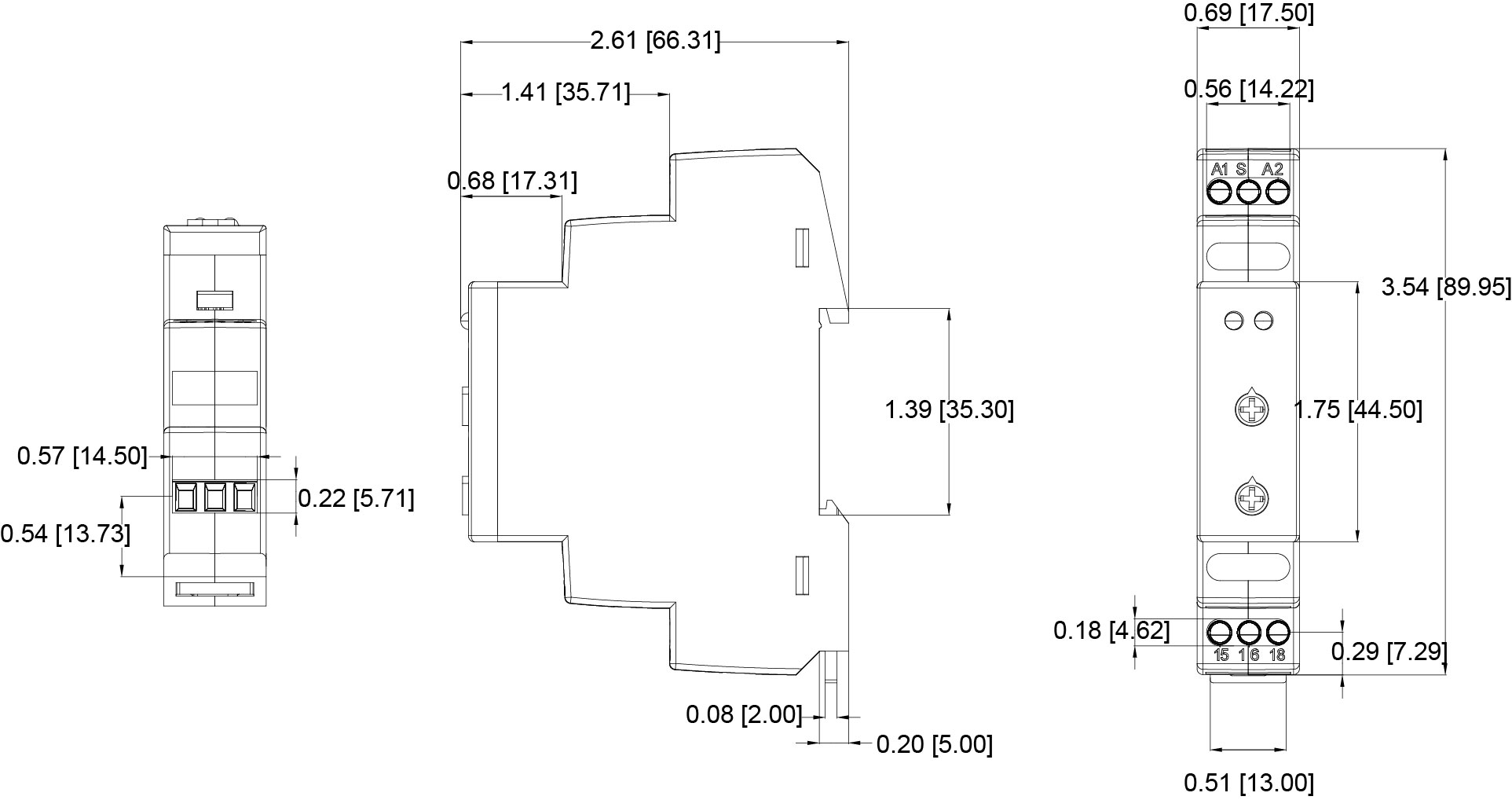
• Mounting: 35MM DIN Rail required, panel mounting with screw not supported
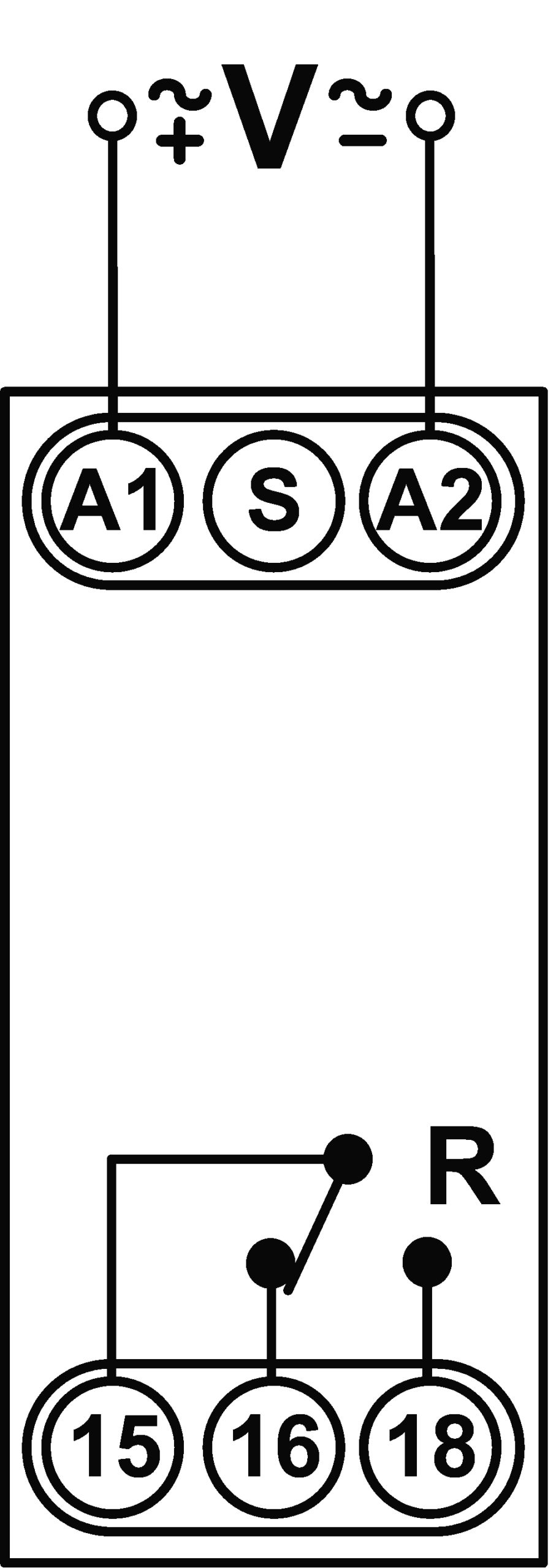
• Wiring:
Flat blade (slotted) screw terminals
Wire Size: 12-22AWG
Maximum Tightening Torque: 4in-lb
Recommend 1/8″ (3 mm) screw drivers


 TE5616U-36